Setup
This chapter will cover the setup of the workshop environment. We will start by installing the necessary tools and setting up the development environment. source
Development Environment
This downloads the rust source code. This is needed to build custom targets targeting a triple-target that is not yet supported by rust.
rustup toolchain install stable --component rust-src
The toolchain for the ESP32-C3
rustup target add riscv32imc-unknown-none-elf
- riscv32imc:
- riscv32: 32-bit RISC-V instruction set architecture
- i: Base integer instruction set
- m: Base integer instruction set with multiplication and division
- c: Base integer instruction set with compressed instructions
- unknown: Vendor field - no specific vendor is targeted
- none: operation system (bare-metal)
- elf: Executable and linkable binary format (calling convenction)
Probe-RS
This is the recommended tool for flashing and and interacting (e.g. debugging) with the ESP32-C3.
NOTE: Package installation for different Linux distributions:
udev rules:
Follow: https://probe.rs/docs/getting-started/probe-setup/#linux%3A-udev-rules
Debian/Ubuntu:
sudo apt install -y pkg-config libudev-dev cmake git
Fedora:
sudo dnf install -y pkgconfig systemd-devel cmake git
cargo install probe-rs-tools
Tools to build a project
To generate a project you need esp-generate.
cargo install esp-generate
To then generate a project run the following command: (TODO: Check, which options are needed)
esp-generate --chip esp32c3 --headless -o probe-rs -o defmt hello_world
You can see all the other options you can use to generate a project here
Flashing
cargo run --release
Board Specs
We use the ESP32-C3 from seeedstudio.
ESP32-C3 Specifications
- Processor: ESP32-C3, 32bit RISC-V singlecore processor that operates at up to 160 MHz
- Memory: 400KB of SRAM, and 4MB of on-board flash memory
- Interfaces: 1xI2C, 1xSPI, 2xUART, 11xGPIO(PWM), 4xADC, 1xJTAG bonding pad interface
Pin Layout

Where do you get the boards from:
Overview on embedded software
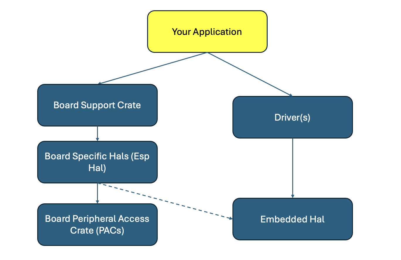
- You application that uses different drivers
- The drivers depend on the embedded_hal
- embedded_hal(_async): for platform agnostic drivers
- Your specific board—that implements the embedded_hal traits. For example esp_hal.
- Sometimes there is a board support crate, with higher level of abstraction than the one of the HAL.
- PACs: The peripheral access crate is a safe rust wrapper around low level memory mapped registers. Generated from System View Descriptions (SVD) files, describing the register map for each peripheral (GPIO, ADC, I2C etc.). SVDs are given from the manufacturer.
Layers of Abstraction
From Comprehensive Rust
Showcasing setting a pin high and low - with highest level of abstraction to lowest
What's a Hardware Abstraction Layer (HAL)?
Abstracts away hardware specifics - e.g. GPIO pins, Timers etc.
#![allow(unused)]
fn main() {
use esp_hal::clock::CpuClock;
use esp_hal::gpio::{Level, Output, OutputConfig};
use esp_hal::main;
use esp_hal::time::{Duration, Instant};

// ... main

    let config = esp_hal::Config::default().with_cpu_clock(CpuClock::max());
    let peripherals = esp_hal::init(config);

    // GPIO 10 is labeled D10 on the Seed Xiao board
    let mut led = Output::new(peripherals.GPIO10, Level::Low, OutputConfig::default());
}
How can you use Drivers, that use embedded_hal?
As an example: Nerd-Neck:
- Uses
bmi160(6DoF - Internal Measurement Unit) crate. Driver, that uses embedded_hal and is platform agnostic. The constructor/factory function intializes with HAL peripherals (i.e. I2C) - Uses esp32s3, i.e. esp_hal I2C, that implement embedded_hal
Further Sources
Let's write a blinky project
Your task is now to create a small program, that sets the GPIO10 to high and back low in a loop in order to let your LED blink.
Before you connect your LED, make sure its connected to a 150-330 OHM resistor. Otherwise the LED will drain too much current from your board and could potentially damage it.
See the given image from seeedstudio:
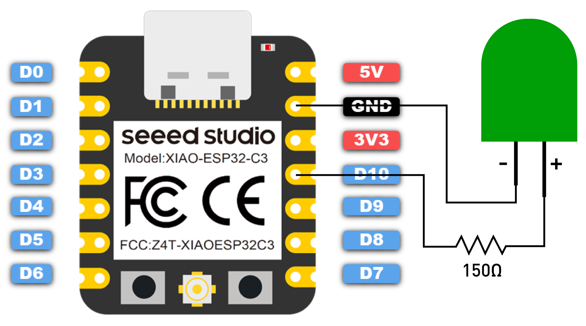 Source: Seeed Studio
Reminder: You start a new esp project with
esp-generate --chip esp32c3 --headless -o probe-rs -o defmt <name of your project>
And
cargo run --release
to flash and run it.
If you are stuck, or want to see the solution: See code/blinky. In the root of the embedded-workshop.
Let's detect a button press
You can also use your GPIOs as input pins, to detect digital highs and lows.
Our board has a boot button. After the boot phase, you can use it as an
input GPIO pin. The Boot button is wired to GPIO9.
You can detect inputs in several ways:
- Polling, if the button was pressed
- Interrupts, if the button was pressed
Polling
To define an input pin with the esp-hal:
#![allow(unused)]
fn main() {
let config = InputConfig::default().with_pull(Pull::Up);
let button = Input::new(peripherals.GPIO9, config);
}
Note: What is a Pull-Up? If the button is not pressed, the input pin will be pulled high to the 3.3V, which is the boards high logic level. If you press the button, the input pin will be pulled low to the 0V, which is the boards low logic level.
You can now try to implement checking the button state with
#![allow(unused)]
fn main() {
button.is_low()
}
in an endless loop (polling), to check, if the button was pressed.
If you get stuck or need help - code/polling is a possible solution.
The interrupt way
Here we use an interrupt to detect a button press.
esp-generate --chip esp32c3 --headless -o probe-rs -o defmt interrupt
cd interrupt
cargo add critical-section
cargo add esp-hal@=1.0.0-rc.0 -F defmt -F esp32c3 -F unstable
If you want to follow along, otherwise the solution is in code/interrupt.
Note: What's an interrupt?
- When an interrupt is triggered, the CPU will pause its current task and execute the interrupt handler.
- After the interrupt handler is executed, the CPU will resume the previous task.
Note: Why is a critical section needed?
- Another interrupt might happend, while we execute our current interrupt.
- It temporary disables interrupts to prevent race conditions.
First we need a dastructure, that is safe to share between interrupts:
#![allow(unused)]
fn main() {
static BUTTON: Mutex<RefCell<Option<Input>>> = Mutex::new(RefCell::new(None))
}
Then we can define our interrupt handler, which is function and acts like a callback:
#![allow(unused)]
fn main() {
#[handler]
fn my_interrupt() {
    critical_section::with(|cs| {
        info!("Button Pressed");
        BUTTON
            .borrow_ref_mut(cs)
            .as_mut()
            .unwrap()
            .clear_interrupt();
    });
}
}
With this defined callback, we then can setup our interrupt:
#![allow(unused)]
fn main() {
let mut io = Io::new(peripherals.IO_MUX);
io.set_interrupt_handler(my_interrupt);
}
At last, we then need to set the correct pin (GPIO9 - our boot button) to our button.
This needs to happen in a critical section, so no one else messes
with our setup in between:
#![allow(unused)]
fn main() {
let mut button = Input::new(peripherals.GPIO9, InputConfig::default());
critical_section::with(|cs| {
    button.listen(Event::FallingEdge);
    BUTTON.borrow_ref_mut(cs).replace(button)
});
}
If you flash and run this with
cargo run --release
You should see the something, if you added an info!(...) print
to your interrupt function, if you click the boot button.
Key Concepts of embassy
What is embassy
Embassy is the next-generation framework for embedded applications. Write safe, correct, and energy-efficient embedded code faster, using the Rust programming language, its async facilities, and the Embassy libraries. Source
TL;DR: It brings Multitasking to the embedded world without an OS on bare metal
Key concepts of embassy
- An executor: A runtime scheduling and running async tasks
- Tasks: Async functions, that yield control when waiting for I/O or timers.
- Everything is bare-metal without any heap - tasks are allocated at compile time.
Let's have a look at code/hello_embassy
The main entry point
The main entry point for an embassy project is its async main.
#[esp_hal_embassy::main]
async fn main(spawner: Spawner) {
    // generator version: 0.5.0

    rtt_target::rtt_init_defmt!();

    let config = esp_hal::Config::default().with_cpu_clock(CpuClock::max());
    let peripherals = esp_hal::init(config);

    let timer0 = SystemTimer::new(peripherals.SYSTIMER);
    esp_hal_embassy::init(timer0.alarm0);
    info!("Embassy initialized!");

    spawner
        .spawn(my_led_blink_task())
        .expect("Could not spawn LED task");
    spawner
        .spawn(my_other_things())
        .expect("Could not spawn my other task")
}
Changes you see from normal bare metal:
- Other macro on top
- No infinite loop in main
- You spawn tasks in this main
The actual work
The tasks then usually carry out the jobs - asynchronous. They are marked async as well and are attributed
by the #[embassy_executor::task] macro.
#![allow(unused)]
fn main() {
#[embassy_executor::task]
async fn my_led_blink_task() {
    loop {
        info!("On");
        Timer::after_millis(500).await;
        info!("Off");
        Timer::after_millis(500).await;
    }
}

#[embassy_executor::task]
async fn my_other_things() {
    loop {
        info!("Other GPIO HIGH");
        Timer::after_millis(1000).await;
        info!("Other GPIO LOW");
        Timer::after_millis(1000).await;
    }
}
}
Communication between tasks
Let's have a look at code/embassy_polling_button.
What is the code doing?
One task polls the state of the your boot button (GPIO9).
If the button state changes, it sends an event. The other task,
waiting for events, will wake up and process the incoming event.
To send such events, we need a so called CHANNEL (global). It's a queue, where
we can enqueue data, and in this case, can hold up to 10 elements in the queue.
#![allow(unused)]
fn main() {
static BUTTON_CHANNEL: Channel<
    embassy_sync::blocking_mutex::raw::CriticalSectionRawMutex,
    ButtonEvent,
    10,
> = Channel::new();

#[derive(Clone, Copy, defmt::Format)]
enum ButtonEvent {
    Pressed,
    Released,
}
}
The sending task (polling button state) gets the sender part of the channel
#![allow(unused)]
fn main() {
let sender = BUTTON_CHANNEL.sender();
}
And the other task the receiving end:
#![allow(unused)]
fn main() {
let receiver = BUTTON_CHANNEL.receiver();
}
The cool thing! The receiver can sleep, until it receives it and event from the queue:
#![allow(unused)]
fn main() {
info!("I am idle and waiting for an event");
let event = receiver.receive().await;
}
The executor runtime will continue the computation of that task, when an event is received.
You can try it out.
Go to code/embassy_polling_task and run
cargo run --release
Interrupts in Embassy
Comparing interrupts with normal bare metal, interrupts in embassy are quite easy.
Embassy directly gives you methods, where you can await for example a falling edge of a given button.
#![allow(unused)]
fn main() {
#[embassy_executor::task]
async fn my_interrupt_awaiting_task(mut input_button: Input<'static>) {
    loop {
        info!("Waiting for a button press");
        // I.E.: When we press the button, the edge will fall
        input_button.wait_for_falling_edge().await;
        info!("I got woken up!")
    }
}
}
The task will be woken up, when we detect a falling edge on that button. This happens, when pressing it, given the following config of the button:
#![allow(unused)]
fn main() {
// Configure GPIO9 as input with pull-up resistor
let config = InputConfig::default().with_pull(Pull::Up);
let button = Input::new(peripherals.GPIO9, config);

spawner
    .spawn(my_interrupt_awaiting_task(button))
    .expect("Could not spawn this task");
}
You can try it out youself. The code is code/embassy_interrupt.
Run
cargo run --release
to build, flash and run it.
More to embassy
If you are interested, what else embassy can do you can have a look at the
Other Embedded Framworks
RTIC - Realtime interrupt driven concurrency
You describe everything in an app module - where you define your local and shared ressources.
- #[local] resources are locally accessible to a specific task, meaning that only that task can access the resource and does so without locks or critical sections.
- #[shared] resources can only be accessed by a critical section (
lock). Whoever has it, cann access the the ressource. Locks are given by priority of the interrupt handlers
#![allow(unused)]
fn main() {
#[rtic::app(device = stm32f4xx_hal::pac)]
mod app {
    use rtic::Mutex;

    #[shared]
    struct Shared {
        counter: u32,
    }

    #[local]
    struct Local {}

    #[init]
    fn init(ctx: init::Context) -> (Shared, Local) {
        // Initialize hardware and return resources
        (Shared { counter: 0 }, Local {})
    }

    #[task(priority = 1, shared = [counter])]
    async fn task1(mut ctx: task1::Context) {
        ctx.shared.counter.lock(|c| *c += 1);
    }

    #[task(binds = EXTI0, priority = 2, shared = [counter])]
    fn hardware_task(mut ctx: hardware_task::Context) {
        ctx.shared.counter.lock(|c| *c += 10);
    }
}
}
Let's write an embassy project: I2C IMU
In this project you will learn how to use the I2C bus to communicate with an IMU (Inertial Measurement Unit) sensor. You will also learn how to find the correct driver library for the sensor you are using and read sensor data with it.
You then can then for example calculate the current orientation of the device, or let an LED blink, if the rotational speed is above a certain threshold.
But that's up to you :)
Setup
Setup
esp-generate --chip esp32c3 --headless -o probe-rs -o defmt -o embassy -o unstable-hal i2c_imu
If you use an ESP32s3:
esp-generate --chip esp32s3 --headless -o probe-rs -o defmt -o embassy -o unstable-hal i2c_imu
Install Xtensa toolchain
espup install --targets=esp32s3
Source the toolchain into your environment
source ~/export-esp.sh
Build and flashing
cargo run --release
What is I2C?
Serial Protocol to transfer data. Needs two signals: SDA and SCL (Serial Data and Serial Clock). Together they build and transfer data between a start signal (S) and a stop signal (P)
To show the data transfer, we can use a diagram.
 Image source: Wikipedia
Within the start (S) and stop (P) signal we can transfer data bits.
Interesting to know is that i2c is a so called master-slave protocol. Meaning, that the master initiates the communication - and the slave(s) respond to the master's requests.
In this case our MCU is the master (that also generates the clock signal) and the peripheral is the slave.
The speeds we can achieve are:
- 100kHz (Standard Mode, 100kbit/s)
- 400kHz (Fast Mode, 400kbit/s)
- 1MHz (Fast Mode Plus, 1Mbit/s)
- 3.4MHz (High Speed Mode, 1.7-3.4 Mbit/s)
More info to i2c you can find at Wikipedia.
How to wire i2c with the ESP32
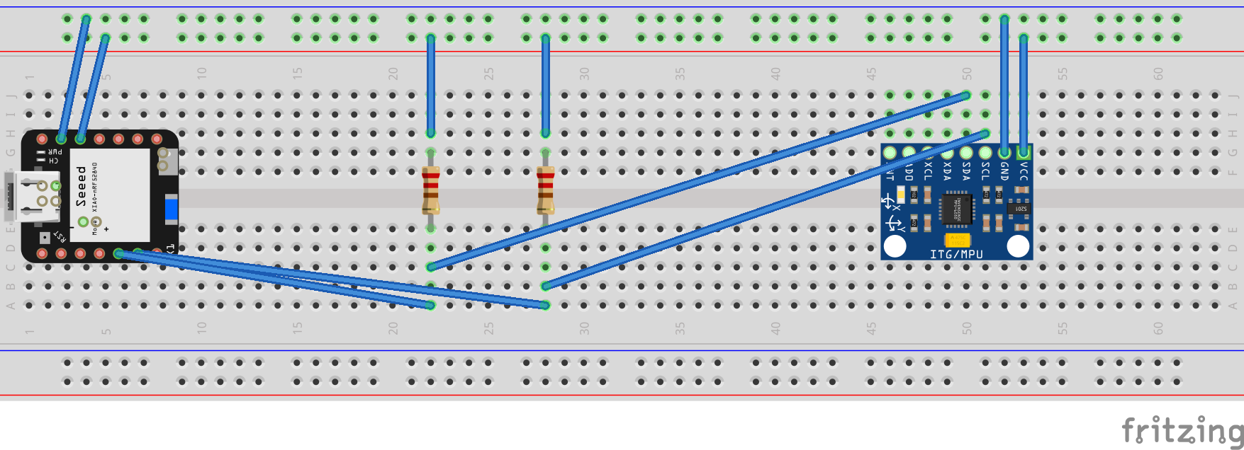
Note: The two pull-up registers in this diagram are very likely redundant since almost all I2C breakout board include them already. But if you put resistors like in the diagram, use 4.7k Ohms resistors, to make the I2C work.
Finding a driver for given IMU
If you are not familiar with cargo crates, you can have a look at crates.io and type in mpu6050, as this is the sensor we are using.
As we also use the quite new embedded-hal crate - it is beneficial, if you filter the found crates for Recent Updates.
You then add the crate with cargo
cargo add <crate-you-found>
Try to implement it yourself
You will find plenty of examples in the crates you chose to for this project.
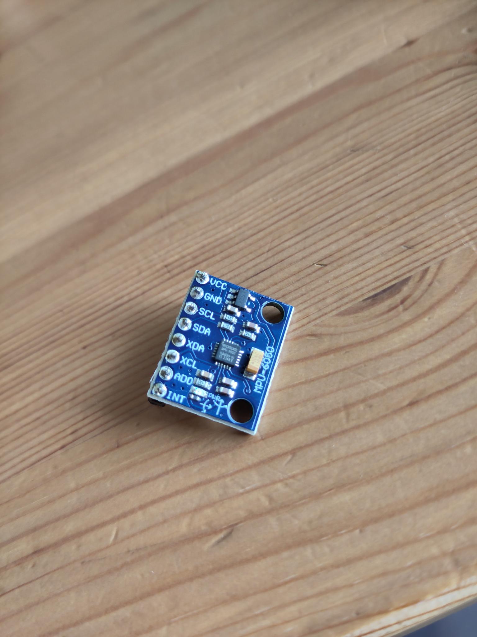
Note: If happen to have an IMU like shown in the image below - those hang up, if you calibrate them. Just leave the calibration out, reading values works.
Netherless: here are some hints, if you get stuck somewhere:
What to do/try:
This should be your steps:
- Find a crate that supports the MPU6050 sensor.
- Look at the examples they provide - maybe you get a hang of how this works
- Initialize an i2c connection using the crate.
- Read the sensor data using the crate.
The crate to use:
We found those two crates useful:
Note: The mpu6050 crate is a bit dated. If you want to use it, make sure you directly
use the master branch of it. Atleast this version complies to embedded-hal >= 1.
We recommed to go for the mpu6050-dmp crate, as it provides a more complete examples and
also supports asynchronous operations.
E.g. Installing the mpu6050-dmp crate
cargo add mpu6050-dmp -F async -F defmt-03
Initializing an i2c connection:
#![allow(unused)]
fn main() {
let i2c_config = Config::default().with_frequency(Rate::from_khz(400));
let i2c = I2c::new(peripherals.I2C0, i2c_config)
    .expect("Failed to initialize I2C")
    .with_sda(peripherals.GPIO5)
    .with_scl(peripherals.GPIO6)
    .into_async();
}
If you get totally lost, we provided you a possible solution at code/i2c_imu_s3 (esp32s3) or code/i2c_imu_c3 (esp32c3), where we calibrate the IMU and read the sensor data. You can also use this one, if you want to continue building something bigger on it.
You can also ask us and others for help!
Let's write an embassy project: Buddy System
What is the buddy system?
Basically: Have an MCU and an embedded Linux system work together. They each do what they can do best and communicate to keep in sync.
As an example, think of a Raspberry Pi ("big buddy") connected to an ESP32 MCU ("tiny buddy") via some serial bus (USB, UART, etc.). The MCU does what it does best: Real-time control jobs with deterministic timing, low-power operation, etc. The Raspberry Pi also does what it does best: Run expensive algorithms, render a UI on a display, manage secure networking, etc. They talk to each other via the serial connection.
Why choose the buddy system?
You may ask yourself one or more of these questions:
- Isn't that more expensive to produce?
- Doesn't that lead to a more complex codebase?
- This seems dumb
Yes, the hardware costs are higher, but for low production runs, the R&D costs usually far outweigh the cost of a Raspberry Pi chip or similar.
Yes, this requires two builds for the firmware and software, but we have embedded Rust now and can write it all in one codebase. In this project you'll see the MCU and the host literally use the same common enum to de-/serialize messages.
Also, OTA (over-the-air) updates on an MCU are scary! Screw one up and you'll be soldering an USB connector to your hardware to re-flash the firmware. Compare that to just doing a deployment on a Linux system that also flashes the firmware on the MCU via it's USB connection and can restart if it fails.
Postcard
Postcard is a protocol designed for communication in constrained environments. It integrates flawlessly with Serde and is resource efficient enough to run on our tiny buddy.
Postcard comes with a lot of features and even with an RPC library. Today we'll mostly use it's de-/serializing and COBS (Consistent Overhead Byte Stuffing helps frame the packets sent on the serial bus.) implementation:
#![allow(unused)]
fn main() {
#[derive(Debug, Serialize, Deserialize, Format, Clone, Copy)]
pub enum Message {
    Button(bool),
}

// ...

let message: Vec<u8, 128> = postcard::to_vec_cobs(&Message::Button(button_state))?;

// ...

let message: Message = postcard::from_bytes_cobs::<Message>(&mut buffer)?;
}
USB CDC on the ESP-C3
The ESP32-C3 has an USB controller that supports USB CDC serial communication (and acts as a JTAG probe):
#![allow(unused)]
fn main() {
use esp_hal::usb_serial_jtag::UsbSerialJtag;

let usb_serial = UsbSerialJtag::new(peripherals.USB_DEVICE);
let (mut usb_rx, mut usb_tx) = usb_serial.split();

_ = tx.write(&buffer);
_ = tx.flush_tx();
}
serialport on the big buddy
On the host side we'll use the serialport library:
#![allow(unused)]
fn main() {
let ports = serialport::available_ports()?;

for port in ports {
    if let SerialPortType::UsbPort(info) = &port.port_type
        && info.vid == 0x303A
        && info.pid == 0x1001
    {
        println!(
            "Using {} at {}",
            info.product
                .clone()
                .unwrap_or_else(|| "[No Product Name]".to_string()),
            port.port_name
        );

        let mut port = serialport::new(port.port_name, 115_200)
            .timeout(Duration::MAX)
            .open()?;
        let mut reader = BufReader::new(&mut port);
        let mut buffer = Vec::new();
        reader.read_until(0x00, &mut buffer)?;
    }
}
}
Great Crates for embedded development
Other tools
- Combining
esp_printlnwith the android appserial_usb_terminalby Kai Morich: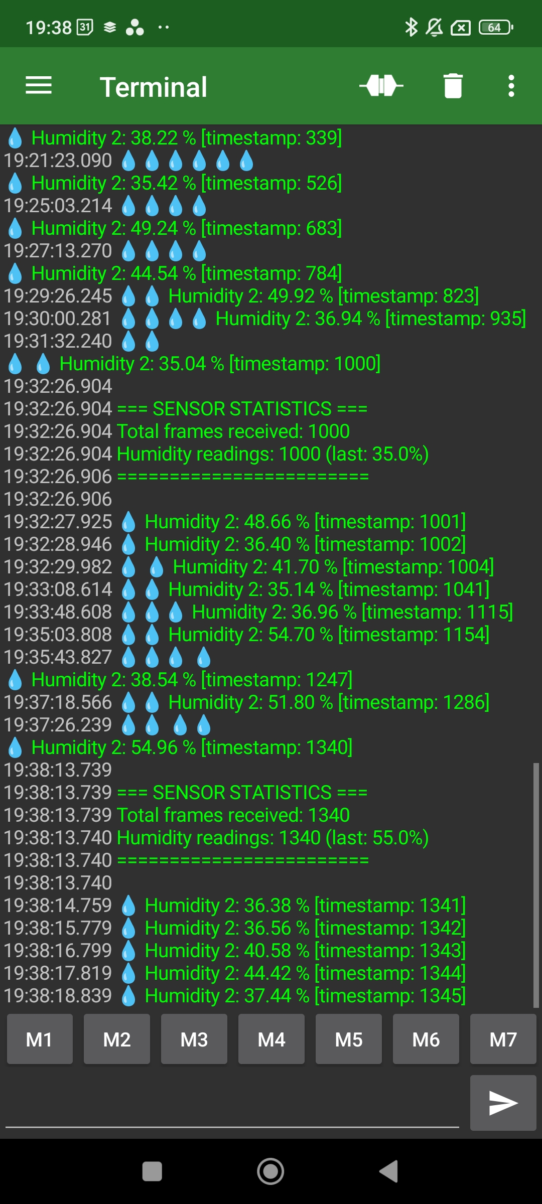 Just plug in USB and tap the 'connect' icon
More I2C sensors
More sensors to implement for the fast and interested are listed here.
Note that we have one of each of these sensors.
PN532 (I2C mode)
NFC RFID reader
https://lib.rs/crates/pn532
INA226
Current and power monitor
https://lib.rs/crates/ina226-tp
AS5600 (and AS5600L)
Digital magnetic potentiometer
https://lib.rs/crates/as5600
PCA0548A
I2C multiplexer
https://lib.rs/crates/pca9548a
https://lib.rs/crates/xca9548a
SSD1306
OLED display
https://lib.rs/crates/ssd1306
TCS34725
RGB sensor
https://lib.rs/crates/tcs3472
BME280 / BMP280
Temperature, (humidity if BME), and atmospheric pressure sensor
https://lib.rs/crates/bme280
Sources
Usesfull resources: